Apple 61W USB-C Power Adapter A1718
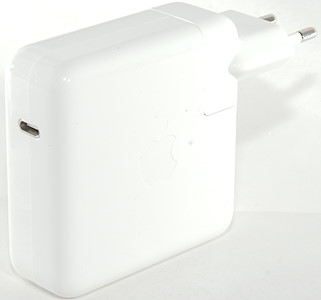
Official specifications:
- USB-C
- 61W
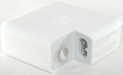
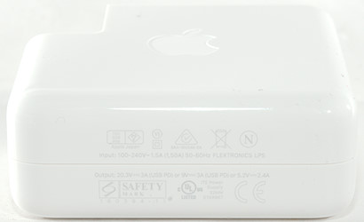
- On the charger with small text and low contrast the actual voltages and currents are listed.



Apple uses a white cardboard box, some of the print is very small and low contrast.
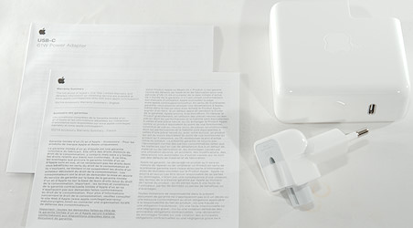
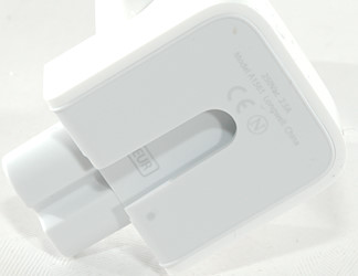
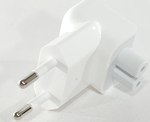
The box contained the charger, instruction sheet and mains plug.
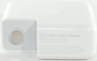

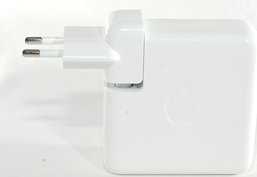
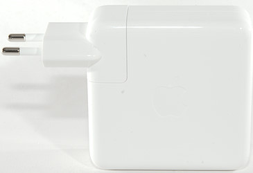

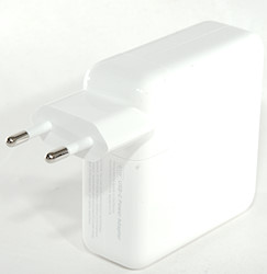
Measurements
- Power consumption when idle is 0.06 watt at 230VAC
- PD modes: 5V 2.4A, 9V 3A, 20V 3A (12V & 15V are missing)
- Default state for usb output is off.
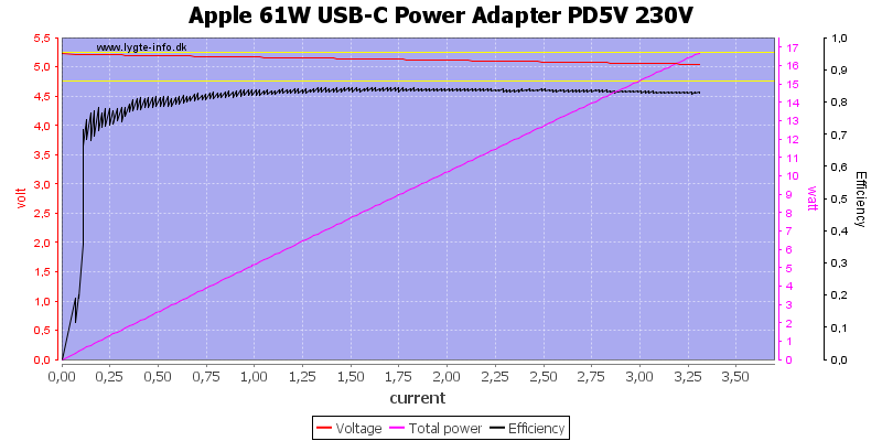
It is only rated for 2.4A, but can deliver nearly 3.3A.
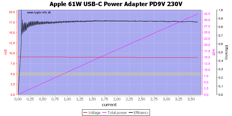
9V is rated for 3A and can easily deliver that.
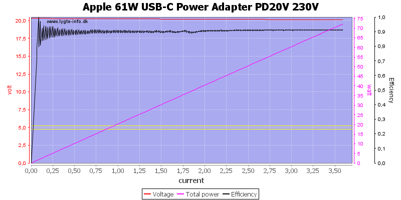
20V is also rated for 3A and can also easily deliver that.
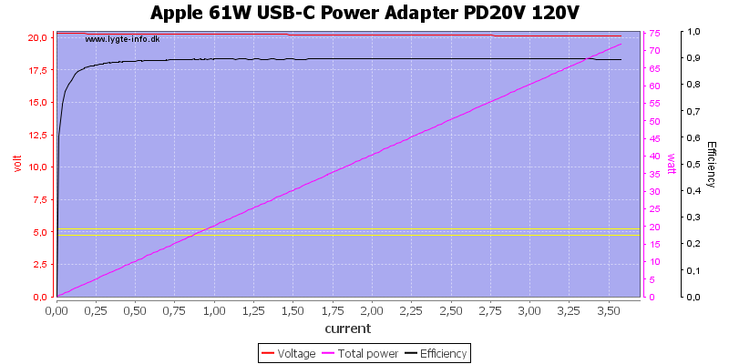
Running at 120VAC do not change anything.
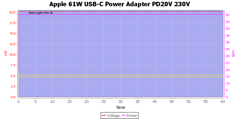
Running at 20V 3A for one hour is no problem.
The temperature photos below are taken between 30 minutes and 60 minutes into the one hour test.
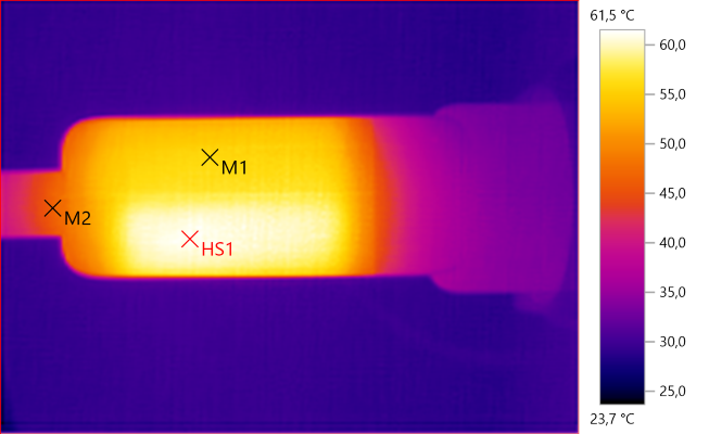
M1: 56.0°C, M2: 46.5°C, HS1: 61.5°C
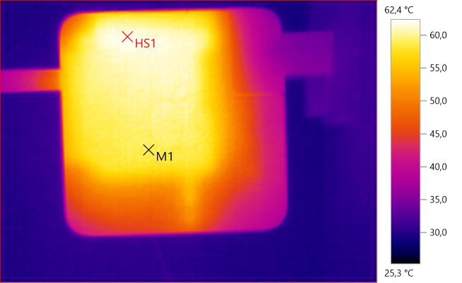
M1: 59.1°C, HS1: 62.4°C
The charger has some metal plates inside to distribute the heat.
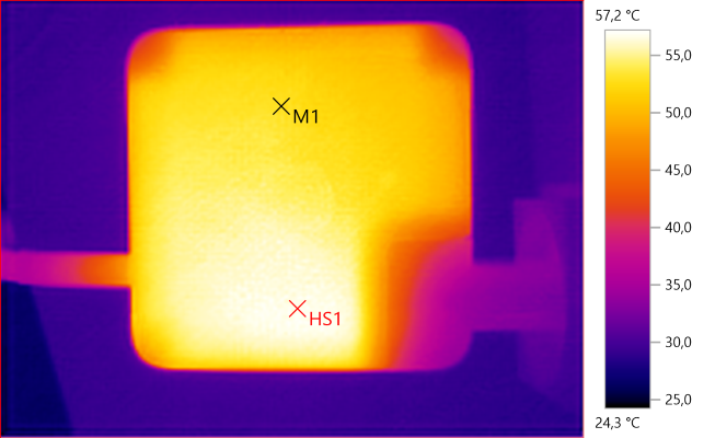
M1: 53.3°C, HS1: 57.2°C
HS1 is the transformer.
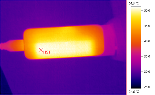
HS1: 51.3°C
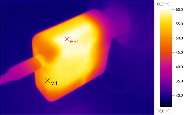
M1: 54.2°C, HS1: 60.5°C
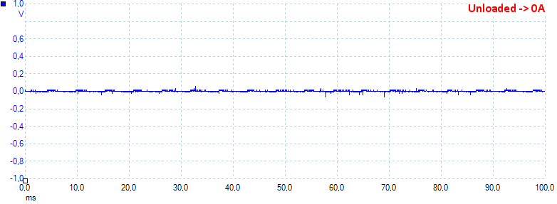
Unloaded the noise is 6mV rms and 169mVpp

At 0.5A the noise is 7mV rms and 167mVpp

At 1A the noise is 6mV rms and 140mVpp

At 2.5A the noise is 10mV rms and 181mVpp
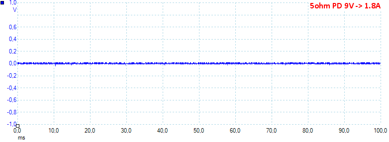
At PD 12V 2.4A the noise is 6mV rms and 117mVpp
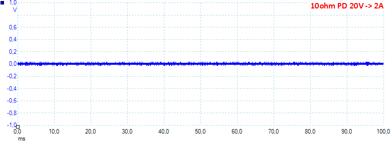
At PD 20V 2A the noise is 15mV rms and 166mVpp
Tear down
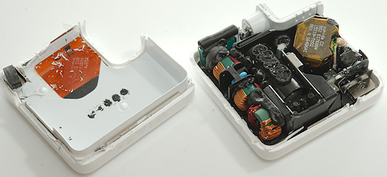
Apple has some very good glue, I could not break this open and had to cut all the way around
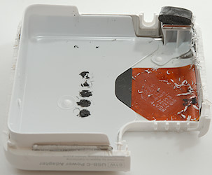
The is some shielding on the inside with a layer of isolation on top of it.
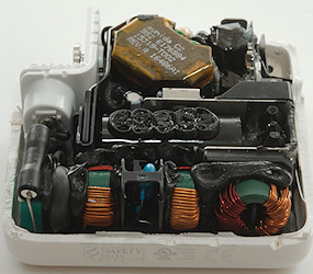
The circuit board is still fixed in the other part
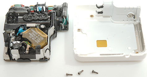
There was 3 screws holding it in.
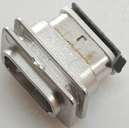
I did break the usb connector off, is was mounted in the plastic and used some flexible circuit board to connect it.
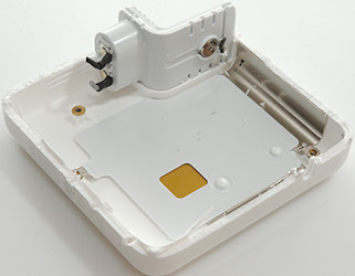
This side do also have some shielding and 3 threads embedded in it.
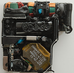
With all the black filler and black circuit board it is not easy to see what is going on, but some of it is possible to see.
At the mains input is a fuse stacked on top of a capacitor, after the fuse is a MOV for transient protection. After that is 3 common mode coils, parallel with the last is a large flat bridge rectifier on a heatsink. There is a large smoothing capacitor, then the next part of the heatsink with mains switcher transistor. Beside the mains switching transistor is the blue safety capacitor, there is only two small smoothing capacitors on the secondary side, both packed in isolation tape.
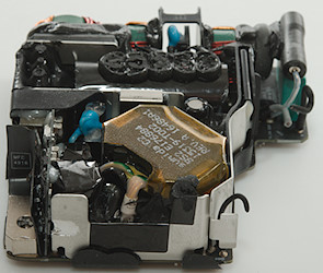
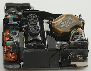
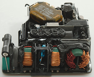
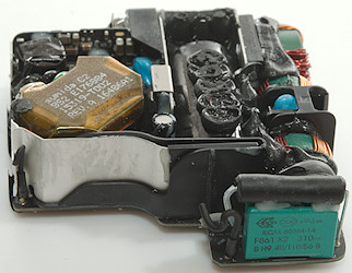
On the second picture is a piece of metal, it may be shielding, but is probably also used as heatsink.
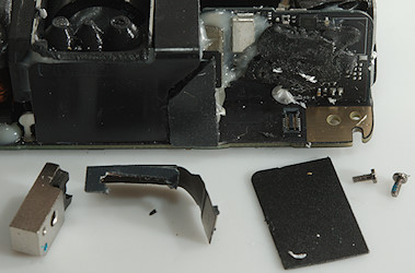
The flexible circuit board from the usb connector goes to a small connector on the circuit board, I had to remove two very small screws to get access.
There is a circuit board behind the connector.
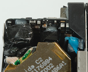
The small circuit board seen from the other site.
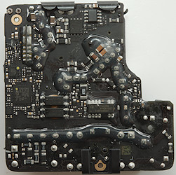
The mains switcher controller is a fairly large chip that is missing some legs (Marked FL?T13A2050) with two optocouplers for feedback from the low volt side near it.
Below the transformer is a synchronous rectifier controller and a smd powermos for rectification. Near the usb port is the usb controller (CYPD2134) and a processor (STM32F071CBU7: 32bit ARM).
The amount of computing power in this power supply looks rather high, I wonder if it can do more than just supply power (Like electronic serial number, special Apple modes or keeping log of usage).
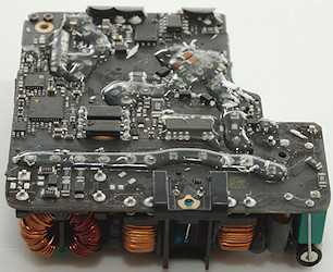
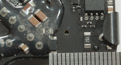
Isolation distance looks fine on the circuit board, but I cannot check the other side. With all the extra plastic isolation place around the circuit board it is probably fine.
Testing with 2830 volt and 4242 volt between mains and low volt side, did not show any safety problems.
Conclusion
This supply has a lot of filtering and this means very low noise on the output. The PD can deliver 61W (Because 20V is 20.3V), I am not that impressed with the PD function, it is missing a lot of voltage and it do have more than enough electronic to implement it.
It is a good power supply, but mostly for Apple equipment, for a more general PD supply I would look at another one.
Notes
Read more about how I test USB power supplies/charger


